Frequency Modulation Atomic Force Microscopy (FM-AFM)
Frequency Modulation Atomic Force Microscopy (FM-AFM) is a way of performing non-contact AFM (nc-AFM) measurements. Briefly, in nc-AFM a sharp tip, which sitting on a cantilever arm, is excited to oscillate in the proximity of a sample surface. The oscillation is directed along the surface normal, i.e., perpendicular to the sample surface. Although the tip never makes direct, physical contact to the surface, the forces between the tip and surface (such as van-der-Waals forces) have an effect on the oscillation characteristics like amplitude and resonance frequency of the tip-cantilever system. Thus, it is possible to quantify the strength of these forces as a function of lateral x-y position of the tip above the sample of interest.
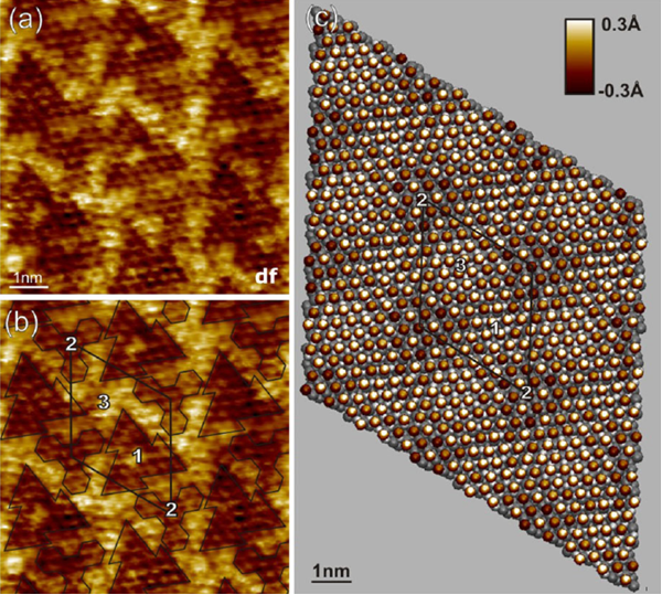
In Frequency Modulation AFM, two quantities are monitored: 1) the individual resonance frequency f of the tip-cantilever system for lateral x-y coordinate above the surface, and 2) the difference df of these values to the unperturbed resonance frequency f0 of the isolated tip-cantilever system: df = f – f0. This quantity df is used as input for the feedback loop that eventually controls the tip-sample distance z: before the experiment starts, df is set to a pre-defined set-point, which is to be maintained by the feedback loop by variation of z.
To monitor the resonance frequency f for each lateral x-y position, a phase-locked-loop (PLL) is utilized to ensure that the tip always oscillates in resonance, regardless of its position and the strength of the forces acting upon it.
When the scanning process starts, the tip visits different lateral x-y positions, each one associated with a unique resonance frequency. The feedback loop then changes the distance z such that the difference between this resonance frequency and the unperturbed resonance frequency f0 remains at the pre-defined set-point value for df. These z-values associated with the x-y coordinates make up the FM-AFM image.


